English
 Chinese
categories
-
9mm 2ml Short Tread HPLC Autosampler Vial 9mm Short Thread Caps with Septa 8-425 2ml Screw Neck HPLC Autosampler Vial Screw Caps with Septa for 8-425 Screw Neck Vial 10-425 Screw Neck 2ml HPLC Autosampler Vial 10-425 Screw Caps with Septa 11mm Crimp Top 2ml Autosampler Vial 11mm Crimp Top Caps with Septa 11mm Snap Ring 2ml Autosampler Vial 11mm Snap Top Caps with Septa
-
20mm Crimp Top Aluminum Caps with Septa 18mm Screw Headspace Vial 20ml Headspace Vials Butyl Rubber Stopper for 20mm Crimp Vials 20mm Crimp Top Aluminum Caps 20mm 20ml Crimp Headspace Vial 18mm 20ml Screw Headspace Vial 20mm 10ml Crimp Top Headspace Vial 18mm 10ml Screw Headspace Vials 20mm 6ml Crimp Top Headspace Vials for Karl Fischer
-
0.3ml 11mm Glass Crimp Vial with Fused Insert 9mm 0.3ml Glass Micro vial Integrated with Insert Micro Inserts for Hplc Vials 1ml Shell Vial 300ul Micro Insert, Flat Bottom, 100/pk 250 μL 9, 10, 11mm Conical Bottom Vial Insert, 100/pk Aijiren 250ul Vial Insert, Glass Spring Bottom for 9, 10, 11mm Vials 250ul Micro Insert, Flat Bottom for 8-425 Vials 150 μL 8mm Conical Bottom Vial Insert Vial Insert, 150ul, Glass with Polymer Feet for 8-425 Screw top Vial
-
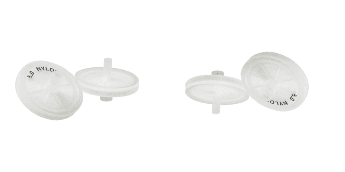
Non-sterile Disposable Syringe Filter Syringe Filter PTFE for HPLC Syringe Filter Nylon for Laboratory Syringe Filter PVDF for Sale Sterile Syringe Filters Wholesale Syringe Filter MCE for Lab Use 0.22μm Pore Syringe Filters for Sale 25mm Syringe Filter for Sale 13mm Syringe Filters Wholesale 0.45μm Syringe Filtre Wholesale Price
-
Comprehensive Guide to Headspace vials:Features, Selection, Price, and Usage Comprehensive Guide to Reagent Bottle Encyclopedia of HPLC vials All About Vial Crimpers: A Detailed 13mm & 20mm Guide Comprehensive Guide to Syringe Filters: Features, Selection, Price, and Usage HPLC Vial Inserts: Enhancing Precision and Sample Integrity Premium PTFE and Silicone Septa: Reliable Sealing Solutions Wholesale COD-V50 16mm 100mm cod tube for water analysis V945 Cheap 2ml 9mm amber HPLC vials for sale V935 Wholesale 2ml amber HPLC vials from China
INQUERY

-
Email: market@aijirenvial.com
-
Tel: 008618057059123
-
Whatsapp:+8618338832256
-
Factory Add: NO.10 Bailing North Road,Qujiang District, Quzhou City, Zhejiang Province,China